
February 2015
Withstanding the heat
Daniele Sciuto,
Euromecc, Italy,
talks through the technical solutions adopted
while designing a cement storage plant that
receives alumina cement at 120°C
Overview
In 2011, Euromecc was selected to design and carry out a turnkey solution for an alumina cement storage plant in Europe by one of the most important contractors in this field. The required storage capacity was around 5000 m3, with pre-arrangement for future improvements, while the key features were related to the product and the management of temperature.
The project
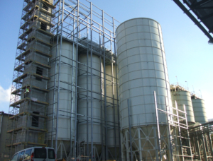
The principal challenge was trying to fit the storage plant to the available site. Euromecc’s technical department drew up several proposals with the aim of ensuring the optimum balance between available space and required capacity. Despite the limited site area, the engineers found a way to store up to 5000 m3 of cement by using different kinds of cement silos. The two main silos have the capacity to store up to 1500 m3 of cement each, and a further four storage silos each have a capacity of 530 m3. There is also a buffer silo above the loading station, which can store a maximum of 120 m’. The project has been developed with the scope to increase storage capacity via two additional cement silos (515 m3 and 300 m3).
Cement is transported from the mill to the storage unit by a pneumatic system, which is connected to a main filter unit that has been designed and manufactured by Euromecc in accordance with the available space and the required specifications. This device can drain up to 9000 m3/hr of air from the pneumatic system and, thanks to its geometry, it allows for the treatment of the fluidised cement. The feed system to the silos begins at the filter. This system is made up of several air slides, which transport the cement that precipitates from the filter and fills the silo selected from the six available. In terms of the discharge, the technical solution includes several extractor screws that reverse the cement into several air slides. Euromecc decided to use both screws and air slides because they are able to compensate for the height difference: although screws need a positive inclination between 20° and 45°, an air slide requires a negative inclination of at least 5 — 6°. Thus, by using both technologies, it has been possible to reduce the required height of the overall structure.
The extraction lines convey the material on two bucket elevators, which are connected to a temperature bypass that checks the cement before authorising its delivery to the buffer silo. According to the temperature, or the required cycle, the buffer is unloaded onto a vibrating screen for a cleaning cycle, after which it could be filled into tankers and wagons through different loading points, or loaded again inside one of the silos.
As can be seen in Figure 1, every component is almost duplicated. This creates two independent production lines that manage grey and white cement while avoiding any product contamination. This also increases the reliability of the plant by ensuring continued operation when a component has to be checked for ordinary maintenance purposes.
Finally, the entire plant is adequately enclosed (Figure 2): the caulked covering protects the plant, enhancing the environmentally friendly nature of the complex and enabling the plant to operate 24/7 without dust emissions or high noise levels affecting the local community.
Adapting to alumina cement
Alumina cement is an aggressive material because of the high presence of Al203, meaning that high wear levels could impact the lifespan of components. When designing the system, a variety of measures were taken in order to reduce the material’s influence on components, the most critical of which were those that had intermittent contact with the cement particles when operating on their different working phases. This includes the components within the main filter unit that receive the material coming from the mill, all the screws, and also the bucket elevators that transport the alumina cement using friction.
The filter is made up of two separate chambers:
the first receives the material from the pneumatic line, while the second contains the filtering elements. The fluidised cement that arrives from the mill has a bulk density of 0.9 t/m3. In order to reach a bulk density of 1.3 — 1.5 t/m3, a proper air drainage system is required to work the air off. It was therefore necessary to equip the contact surface with Hardox wear plates, which have also been installed at the filter discharge area.
The screws that were chosen are short in length in order to avoid the presence of hanger bearings. These have been provided with a special Hardox spiral, which helps to enhance their overall performance.
The bucket elevators were customised by reinforcing the buckets with special anti-wear steel `CREUSABRO 321′, while the joint elements were made from Steel 21Mn4 and C45.
Furthermore, in the silos where the cement does not normally move, the designed thickness of the cones was bigger than standard.
Cooling down
The cement arrives from the mill at a flow rate of 20 tph with a temperature of 120°C. This is quite high for a storage plant and could generate condensation, especially if the external temperature reaches -15°C. It is, of course, important that the condensation does not come into contact with the cement powder.
In order to avoid any issues it is necessary to bring the temperature down. A system that manages a proper cooling cycle was needed to allow cement to flow through the air slides until a suitable temperature was reached.
From CAD to site
Designing such a complex plant has involved several units from the technical and electric departments of Euromecc, which has worked on the project for around 4500 hours. Due to the narrow site area, the engineering department also developed special components and schedules that allowed the erection team to install the whole plant without any problems. The turnkey installation has involved a large number of resources that were managed by several skilled supervisors from Euromecc’s headquarters.
All the supplied items have followed a number of installation steps. They were assembled on a separate, larger site and transported to the main site in an appropriate order. A 3000 m2 scaffolding was then erected in order to allow for the housing erection. The plant subsequently underwent commissioning and testing for two months before it began operating at full speed in June 2013.

 +39 335 7156 777
 +39 335 7320 949
 +39 335 7151 919
 +39 335 6792 771
 +39 342 5439 331
 +49 6190 9376 550


